In process of learning Motion, please help…

So first of all, fox_m's answers have helped me a ton on my Motion journey and I would like to express my gratitude. However, I stumbled upon this answer (How can I get numeric samples into Motion?) and no matter which way I look at it, I just don't get it: as far as I'm aware, X and Y positions are not related in any way that could be used to store values. But defining values would be super useful to me.

My question is as follows: am I misunderstanding something? This seems to absolutely be going over my head. Would anyone be able to clarify what fox_m meant?


Thanks

MacBook Pro 15″

Posted on May 14, 2025 3:29 PM

Reply
8 replies

May 15, 2025 9:32 PM in response to Ugnius_R

There is no way to do "variable value" division in Motion — it's a protection from accidental divide by zero errors.

(It's one of the very few "missing elements" in Motion on my "wish list".)


It took me awhile to find the project I used to build for the suggestion I posted back in January... and what I posted was incomplete — an overview if you will. The process was not pursued so it remains **incomplete**.


Starting over:


Set up your data table with a Bezier path. For however many data entry points you need, just click a control point. Type Return when finished and turn off the fill and outline (or set it to Width 1 and Opacity about 25%).


Go to Shape > Geometry.

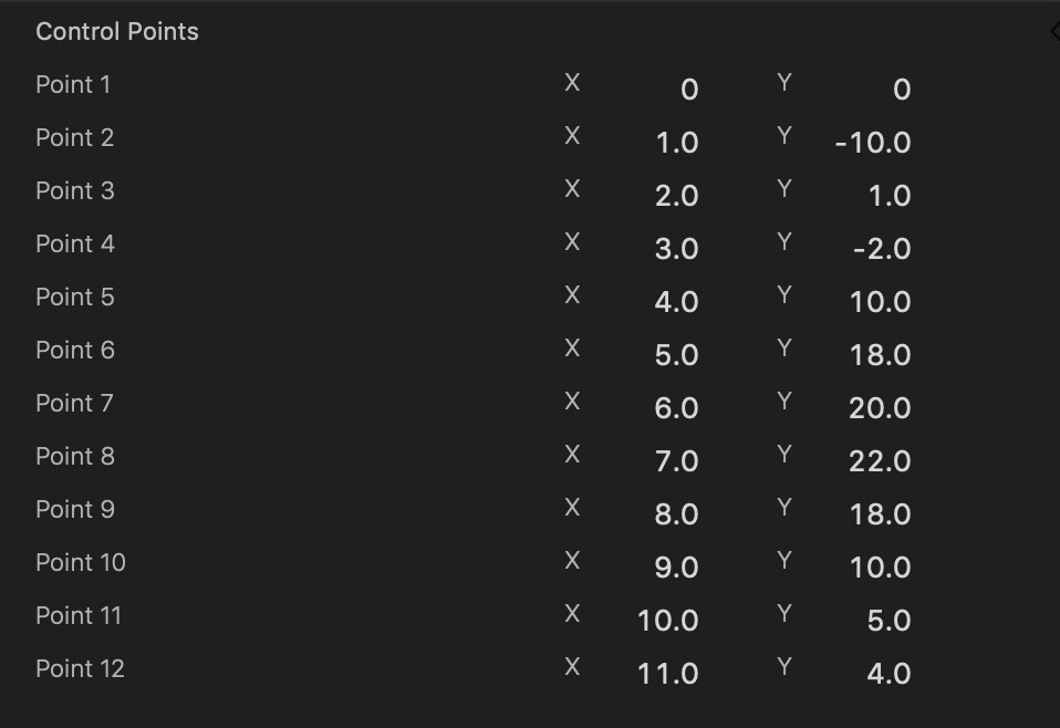
Set all the X points to sequential values: 0, 1, 2, 3... or 0, 10, 20, 30 — what's going to matter is how many control points you have, so the spacing is basically irrelevant (but it helps if they're evenly spaced.)


Set the Y points to the values you need. Here's a sample (temps in C?):


You can use a Null object like a Crosshair, or a shape (name it nullObject) and apply a Behaviors > Basic > Motion Path; set the Path Shape to Geometry and apply the Bezier shape to the Shape Source. **Set the Speed to Natural**.


For this project, use an Onscreen Control for the "lookup" control:

Create another rectangle — doesn't have to be big -- about 200 by 15 or so... call it "CTL"

Add a Filter > Distortion > Poke filter.

To the Center X parameter add a Clamp: Min and Max : 0px to 1px

To the Center Y parameter add a Clamp: Min and Max: 0.5px to 0.5px


Add a Numbers generator (call it CTL value). Turn off Animate and add a Link to the Value.

To the Link Source Object add the CTL rectangle

Source Parameter to Filters > Poke > Center X

Add a Quantize behavior to the Numbers Value

The Step Size will depend on the number of Control Points of the Bezier.

In the example shown above, there are 12 Points. The Step Size will be 100 ÷ (#Points -1)

In this case: 100/11 is 9.0909...


******** Here is an IMPORTANT point about Motion *********

Although you can never see more than 4 decimal points in ANY parameter

Motion accepts and RETAINS* entered values up to 14-15 decimal places

(I'm fairly convinced that a 15th place can be significant, there is no way to prove it is kept

— probably involves the final rounding of the 14th place.)

Therefore, enter 9.090909090909091

[*retains IF you do not select the value again! Otherwise, re-enter the entire value.]


Go back to the Motion Path behavior and for the Offset, Add to Rig > Add New Rig > Slider

Set the Start value to 0 and the End value to 100%.


With the Slider selected, go to Behaviors > Parameter > Link

Set the Apply To to Object.Slider

Set the Source Parameter to Object.Numbers.Value.


The "linkage" goes from the Poke control to the CTL Value to the Slider to the Motion Path Offset.


To finish it off, add another Numbers. To the Value, Link the NullObject > Transform > Position Y for the Source Parameter and set the Scale to whatever the height of your Project is divided by 100. So, if your project is 1080 vertical, then the Scale is 10.8. [You can set up an IndexValue number generator, referencing the Position X of the NullObject and setting the Scale to 19.2 IF your project is 1920 wide...]


Another note about Motion: The graphics going on in the background are on a Square coordinate system (in a 1080vertical project, it is 100x100) and XY values are kept in that space — the Translation to your project will require scaling by the dimensions of the project. [I haven't quantified whether larger project sizes increases the background coordinate system or not...]


As you move the Onscreen Control from left (0) to right (1), the data values should be revealed as the exact values you provided for the Bezier Y points.


Hope this helps! This was a bit complicated, so let me know if I forgot something or you run into trouble.


May 15, 2025 2:56 PM in response to Ugnius_R

Ok - I'm going to assume you want a "selectable database" type object - selecting the month number to reveal the temperature marking. The month selector can be controlled by animation or something like an onscreen control?


For each "month" (or data reference point), create a Numbers Generator (turn off Animate and set the Value to "average temperature" in this case, or whatever you need, later.) I recommend that you *name* each Numbers generator by month abbreviation (it will help keep things straight as you progress.)


This next section is going to get complicated, so I'm only going to take it to 3 samples ("Jan", "Feb", "Mar"), you should be able to easily extend this to what you need. [From a graphics design perspective, 12 values are the high-end extreme. Most charts/graphs should be from about 3 to 7 elements... just saying.]


Create another Numbers Generator and call it ShowVal; turn off Animate.


Right click on Value and Add Parameter Behavior > Link.


Drop the Jan numbers into the Source Object. The Source Parameter should be updated to Object.Numbers.Value automatically, but if it doesn't, set it to that. This is the first value and it will always be "on".


Duplicate the Link behavior. In the Second Source Object, drop the Feb numbers into the Source Object.

[This is where it starts to get interesting].

Set the Custom Mix to 0.


Duplicate the Feb Link Behavior. In the Source Object, drop the Mar numbers into the Source Object. The Custom Mix will already be set to 0.


Continue for each Data Point (month) you're going to be using.


For this next section, you will need yet another Numbers Generator. Call it Selector.


Go back to the beginning (bottom) of the Link Behaviors attached to ShowVal.


FOR EACH Custom Mix = 0, right click and Add Parameter Behavior > Link. Set the Source Object to Selector.

Set Apply Link When to Source value between min and max.


For the first (Feb) behavior, set Value Min to 100 and Value Max to 200.

For Mar, set Value min to 200 and Value Max to 300.

Etc... each successive month will be +100 for each Min/Max as the previous one.


Now, as you increase the Value of Selector from 0 (Jan) to 1100 (Dec), ShowVal will display that month's temperature.


It doesn't end there (but if you make it this far — all the more power to you!)


The best way to deal with Selector is to add its Value parameter to a Rig Slider. Set the Range Minimum to 0 (or 1) and Range Maximum to 11 (or 12) [depending on how you want to refer to the Month number] and with the Slider control all the way to the left, set Selector Value to 0 and with the Slider control all the way to the right, set Selector Value to 1100. Now, when you use the Rig slider, you can move from 0 to 11 and each whole number will display that month's value. [Unfortunately, there's no way I know of to quantize the Rig Slider values — they always display decimal values. You could opt for a Popup menu rig for each month, but that won't be something you can animate. There's also the possibility of an OSC controller... cross that bridge when you get there.]


If you run into any issues... don't hesitate to ask.


May 16, 2025 6:48 PM in response to Ugnius_R

Personally, I'd rather see division by zero go to MaxInt or MaxFloat. It should still be functional.


About the square coordinate system - that, I know for sure BUT the actual coordinate values... not so sure. It could just as easily be 1000x1000 (or more) and there is an argument to be made for that and it has to do with how Numbers is made to "typically" represent values. Quite often, linking a parameter value to a Numbers Value results in a value 10x what it should be (and sometimes 1/10th what it should be). I have MY rationalizations about that... but just conjecture. Since direct access to that coordinate system is not available...


Filter (OSC) controls are "mapped" to their containers and it will depend on what they are applied to: shapes or image objects map to their "bounding boxes". Objects like Text will map to the project dimensions. 2D Fixed Resolution will map to those designated dimensions. Generators (like Color Solid) also map to their designated dimensions.


I guess I'm trying to describe the 0-1 coordinates as a behind the scenes theoretical grid that is *mapped* (conformed) to the dimensions of whatever container it is applied to. The base Center XY values can be considered a percentage of the distances. Since the Center X and Y ranges of values are equal, that suggests a Square base.


I think, for the most part, Motion is *designed* to keep people from dealing with the hardcore math and the "other quirks" involved with all the different aspect ratios, etc.. It's supposed to be a "friendly" motion graphics app, which, it is (and I've used just about all of them at various times over the years.) What is also amazing is that if you really need it and know how to finesse it, there is an amazing amount of capability built in and accessible!!


May 15, 2025 5:41 PM in response to fox_m

Thank you so much for taking the time to answer, but the method isn't exactly what I was looking for. Now don't get me wrong – it works. Matter of fact, I have done something very similar in my testing, but when I stumbled upon your answer to a post here, it made me believe there was a simpler way of data entry and retrieval.

If you're willing to spend all that time typing in values, then there is another way to do the data entry within Motion that will give you X/Y relationships. Just create a shape (any). Turn off the visibility and use it as a "null object".

Set the position at 0,0. Then, for each value you need to enter, go from X -> 1, enter a Y value; move to X -> 2, enter the next value.

For each X position, you can read the Y position. You can manipulate the values with Numbers - using it to move the null shape to the X value, then accessing what the Y value is at that point — in other words:

null shape X position > Link to Numbers(x) Value
Numbers (y) Value > Link to null shape Y position

X values will be progressed by 1 px for each value of Y needed.

On an unrelated note, have you by chance discovered any way to do division or reciprocals in Motion for variable values? So far, I've thrown together a simple concept of Newton's method I'd ripped off from Wikipedia but it needs work on divergence/convergence. Maybe someone has suggestions on other methods that are more effective but are still doable on native Motion (without plugins)?

May 15, 2025 6:16 PM in response to Ugnius_R

In Motion, the X and Y positions of an object are used to specify its location on the screen, not to store numeric values directly. If you need to define values for your animation, you might want to look into using keyframes or rigging parameters to achieve the desired effects. Feel free to ask for more specific help if needed!

May 16, 2025 5:07 AM in response to fox_m

Thank you so much for your in-depth answer. I can finally sleep at night knowing this is indeed possible. I actually have played around with bezier paths recently (for reciprocal approximation (your idea, actually!), but couldn’t find any vectors online that use points with curvature instead of just sharp points that are reasonably large in values) so how I didn’t think of this is beyond me.


Regarding division by zero – I don’t know what would need protecting. I have seen ”NaN” values in Motion and they just get interpreted as 0 (default value?) if I recall correctly. I’m not a conspiracy theorist but I tend to believe the lack of division is partly in effort not to make Motion too powerful to drive the FxPlug market (another thing that has lead me to this conclusion is the template locking flag). But that’s just a theory. A GAM—


One thing that wasn’t exactly clear to me was the Square coordinate system (the 100x100 part to be exact). Are you talking about the fact that for example, most (all?) filters use 0-1 px (translating to, like you implied, -axisDimension/2 — axisDimension/2) values for their center controls? If so, then no – in my experience, both 4K and 1080p projects use the same 0-1 px coordinate system (have not tried other resolutions or aspect ratios but have to imagine they would get scaled the same?). Apart from the Final Cut Pro …quirks of this system (the deriving X through Y …sometimes), I mostly tend not to even notice it anymore. I just do some calculations (I’m not good at math, mind you) and it magically turns out I did those calculations correctly if the values do what I want them to do.


Again, thank you so much for digging through your files for me and the really thorough explanation. This is for sure not only going to be useful for me but for others as well!

In process of learning Motion, please help…

Welcome to Apple Support Community
A forum where Apple customers help each other with their products. Get started with your Apple Account.